
Led Strobe Schematic Power Amplifier and Layout
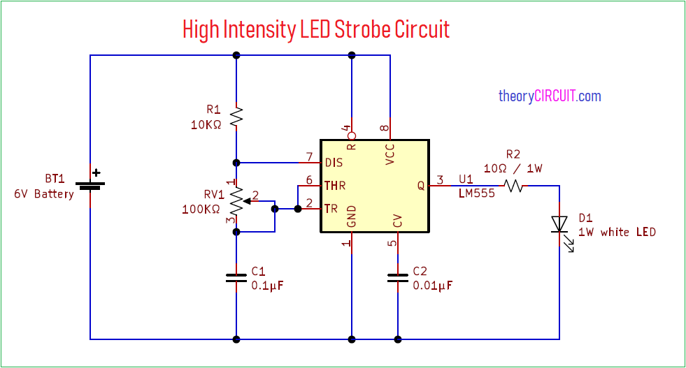
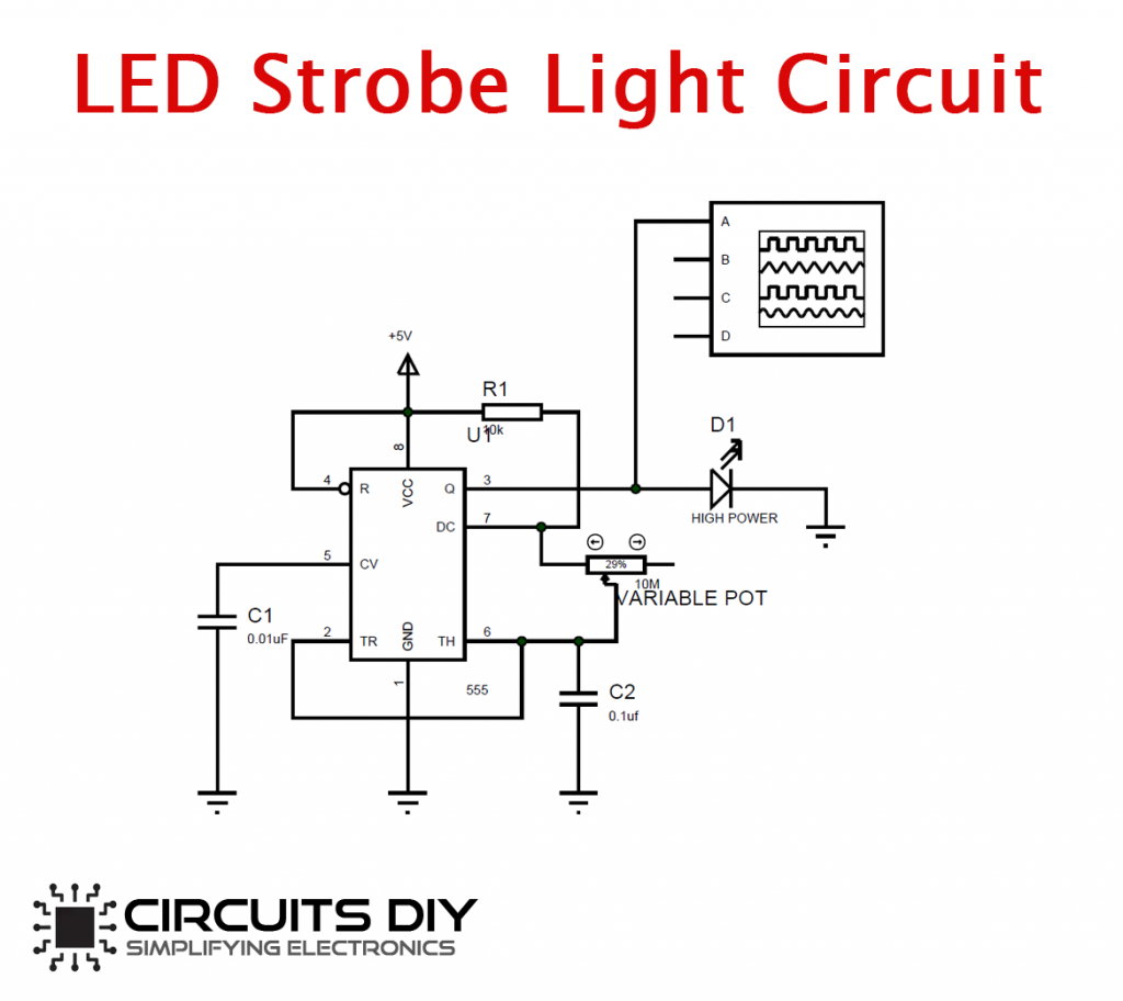
5 Working Explanation In this tutorial, we will show you how to make an LED Strobe Circuit using 555 Timer IC. Strobe light produces regular flashes of light in order to create a stroboscopic effect. In this circuit, we will be using a 1-watt high-intensity LED for the effect to be clearly visible.
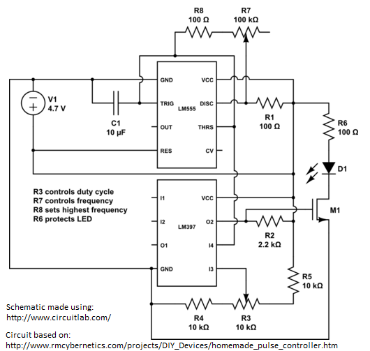
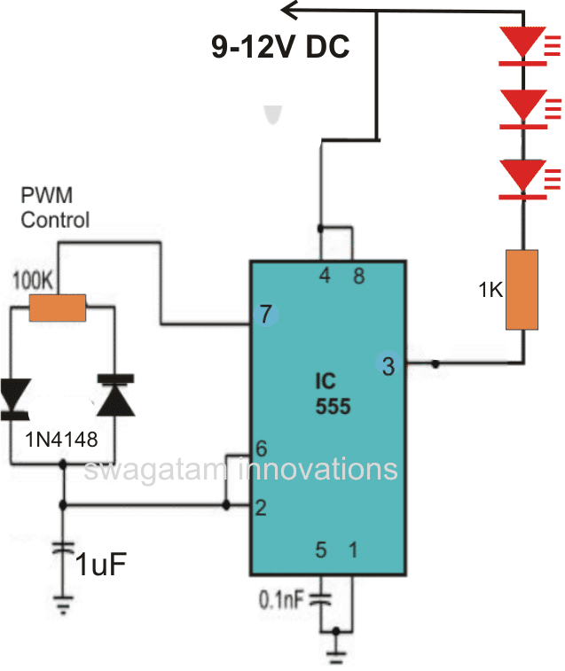
Variable Duty Cycle LED Strobe
From the negative side of the capacitor, connect a resistor in series with an LED. Repeat this process with multiple LEDs until you have the desired number of lights in your circuit. Finally, connect the negative terminal of the battery to the negative side of the last LED. Once all the connections are made, turn on the switch, and voila!
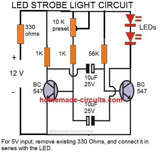
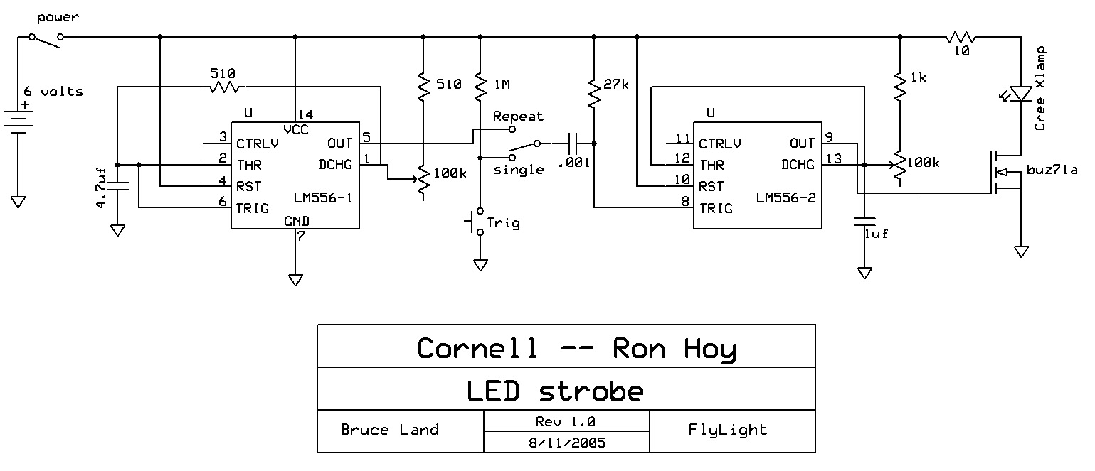
How to Make Any Light a Strobe Light Using Just Two Transistors
LED strobe lights typically consist of a power source, a control circuit, and one or more LEDs. The power source provides the necessary electrical energy to drive the LED, while the control circuit regulates the flow of current to create the desired flashing pattern.

35 Unique Third Brake Light Wiring Diagram Strobe lights, Strobing
ETD is one of the largest suppliers of Emergency vehicle lights for first responders. Our LED Strobe lights are manufactured to the highest standards and meet or exceed all existing operating safety codes. Our police and emergency vehicle sirens are waterproof and built to last. Whether you are outfitting a POV or an entire fleet with police.
How To Make A Led Strobe Light Circuit Using Arduino Wiring Diagram
In this project let us develop an LED Strobe light circuit using the popular 555 timer IC. A strobe light or a stroboscopic lamp is one which can produce regular flashes of light. We are designing this circuit using a 555 timer for setting the delay between each flash and a high power LED light as the source of light.
Simple 1 Watt LED Driver Circuit
30 Day Money Back Guarantee - Same Day Shipping - Dedicated Customer Support. High Intensity Rotating Beacon Great For Improving Safety.
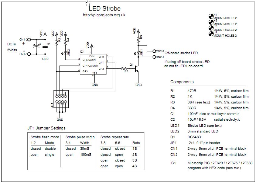
LED Strobe
A typical LED strobe light schematic consists of one or more panels of high-powered LEDs, connected via a power supply and control board. The power supply provides the current needed to run the LEDs, while the control board allows for dimming, flashing, and color changing effects. The resulting patterns can be both simple and complex, depending.

LED Strobe Light Circuit with NE555 Tutorial YouTube
Zener diode - 5.1 volts, 400 mW = 1 LEDs - Red, Green, Yellow 5mm IC 555 = 1 IC 555 Pinouts Video Demo Creating Flashing and Fading LED Effects using IC 555 Circuit The first figure shows the basic configuration associated with a 555 IC LED circuit. Here it is connected as an astable multivibrator.
LED Strobe Light Circuit Electronics Projects
Step 1: Watch the Video! The videos gives you all the information you need to create your own LED Stroboscope. During the next steps though I will present you some additional information. Ask Question Step 2: Get Your Components! Here you can find a parts list with example seller for the 555 Timer circuit (affiliate links): Aliexpress:
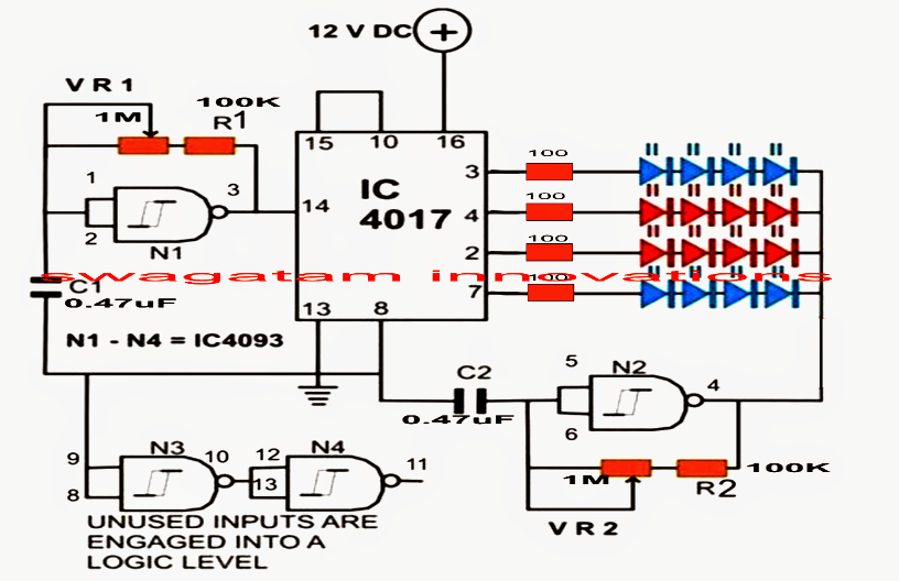
LED Strobe Light Circuit with Chasing, Flashing Effects Circuit
The LED panel comprises twelve white SMD LEDs (WLED1-12), actually a parallel combination of six WLED strings (one strings holds two series-connected lamps). See its circuit diagram below. The entire hardware setup is prepared to run on any 12V DC unregulated/regulated power supply capable of delivering minimum 1A current at 12V.
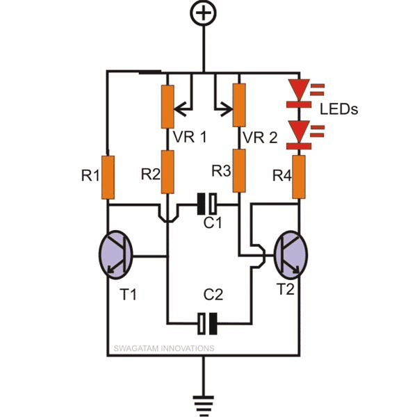
How to Make Any Light a Strobe Light Using Just Two Transistors
A LED strobe light is a type of lighting device that produces regular flashes of light at high frequencies. It is typically composed of several light-emitting diodes (LEDs), which can be programmed to produce different patterns, colors, and intensities of light.
LED Strobe Light Circuit with Chasing, Flashing Effects Homemade
As mentioned before, an LED strobe certainly needs a powerful LED light source for most common applications. In the above figure, what you see is a cool-white 50W COB LED module once I got it from a Chinese online store. The COB (Chip On Board) simply denotes that this module has a number of LED chips in one package as a single module.
LED + 555 timers => BRIGHT strobe Hackaday.io
1 Hardware Component 2 NE555 IC Pinout 3 LED Strobe Light Circuit 4 Circuit Operation 5 Applications and Uses In this short DIY tutorial, let's build up a LED Strobe light circuit utilizing the mainstream 555 timer IC. A strobe light or a stroboscopic light is one that can create uninterrupted flashes of light.

HighBrightness LED Strobe Using IC 555
These DIY projects certainly show a schematic diagram on building a LED Strobe Control Circuit using 555 Timer IC, flashing 2 LEDs with an external circuit, as well as the circuit design.
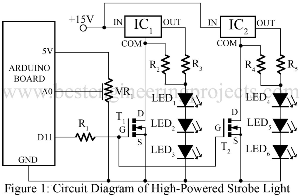
High Powered Strobe Light Using Arduino Best Engineering Projects
1. Transistor Method 2. Timer IC 555 method You've come to the right site if you want to learn more about DIY strobe lights and how they operate. Introduction A stroboscopic gadget produces strobe effects. Simply put, an LED strobe light emits intense bursts of light. It creates a steady, powerful burst of light.
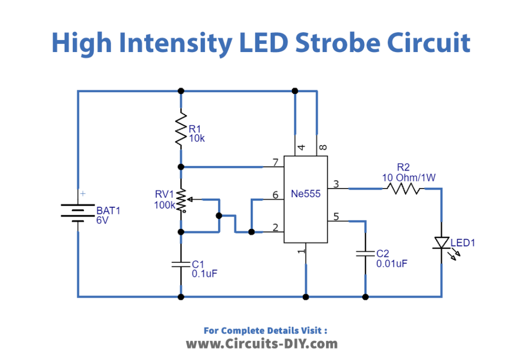
High Intensity LED Strobe Circuit
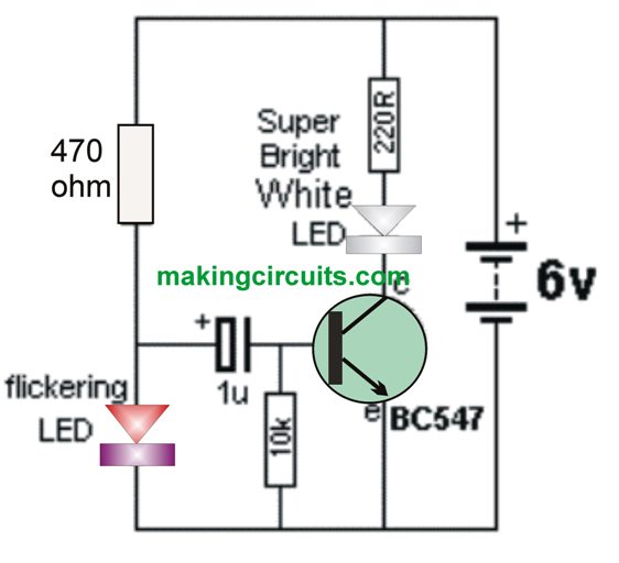
Simplest Strobe Light Circuit Last Updated on January 10, 2018 by admin 3 Comments A very simple strobe light circuit can be built using a single transistor and a high bright white LED, in conjunction with a flickering LED.
