Emergency Lighting Schematics Circuit
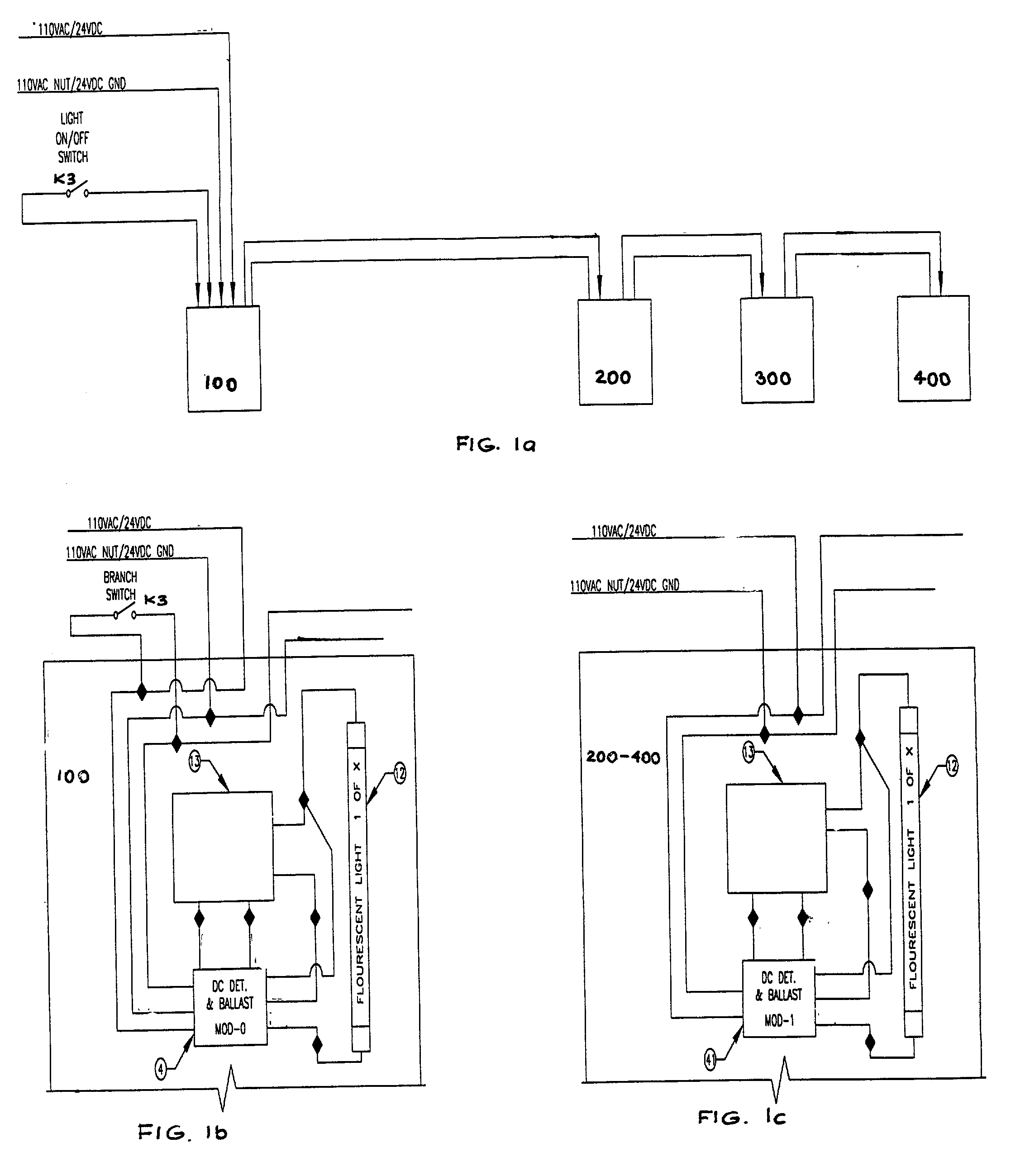
If you know the actual model number of the AC ballast that the emergency unit is being wired to, you may use the "FIND" tool in the toolbar (Denoted by the binocular icon) to search the diagrams for that particular model. FIND commands may or may not be suc- cessful, since not all ballasts models are listed within this file.

Emergency Lighting Wiring Diagram alternator
central emergency lighting power, suitable for traditional emergency power sources (diesel generator and slow transfer inverter backups) in addition to fast-transfer (FT) inverters or uninterruptible power systems (UPS).. Figure 01 - Example Wiring Diagram: rPP20 DS 24V ER EFP G2 Figure 02 - Example Wiring Diagram: nPP16 D ER EFP.
️Emergency Light Remote Head Wiring Diagram Free Download Gambr.co
The diagram you use should match the type of emergency lighting system you plan to install. For example, if you are wiring a system with single-pole lights, you'll need a different diagram than if you're wiring a system with double-pole lights.
21 Lovely Emergency Light Key Switch Wiring Diagram
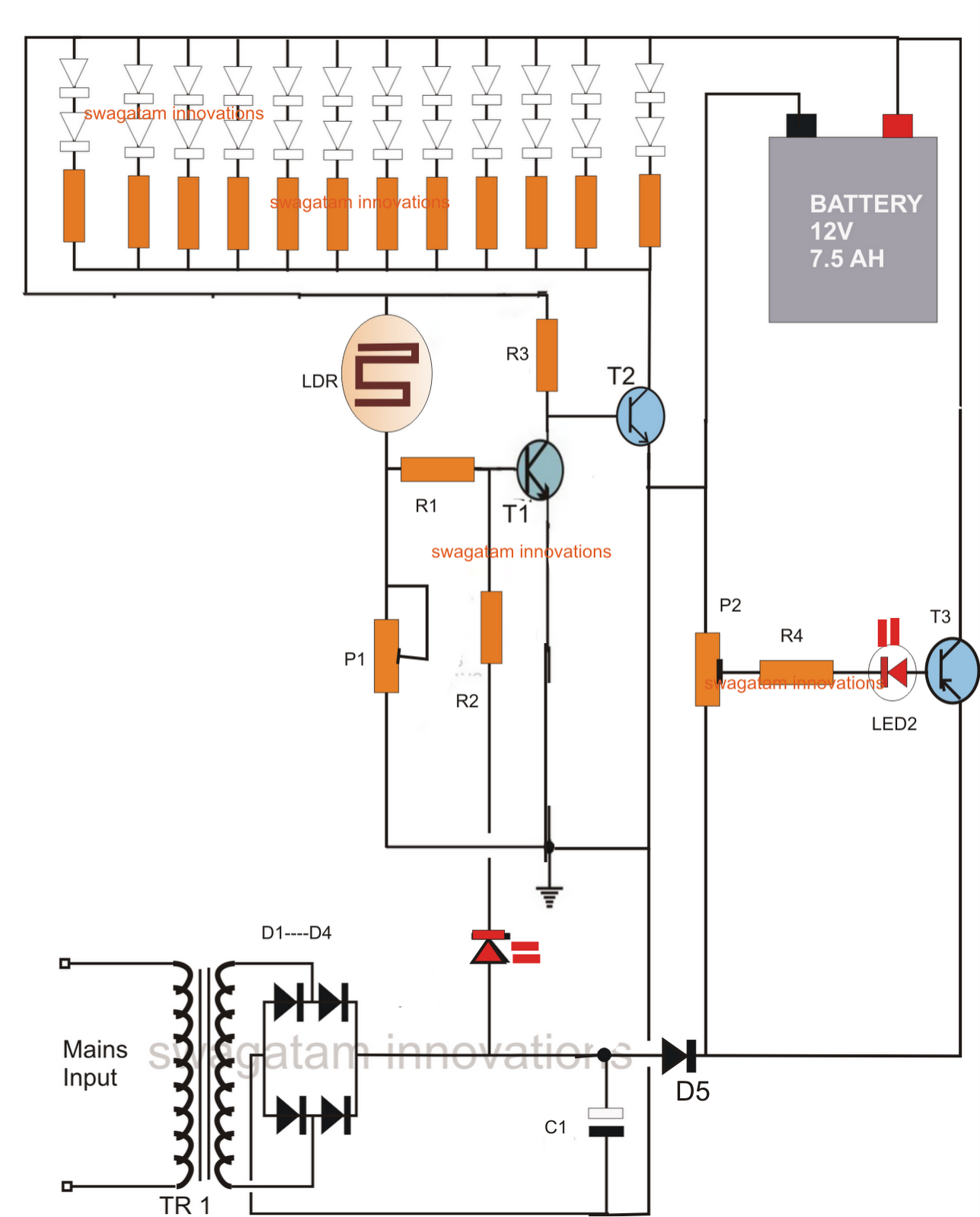
Circuit Explanation We can divide this LED emergency light circuit into two parts; first part is used to drop down the 220v AC voltage into 8v regulated DC, with the help of Transformer and bridge rectifier. And second part consists of Relay and rechargeable battery, which is used to lighten the LEDs during power failure. Components:

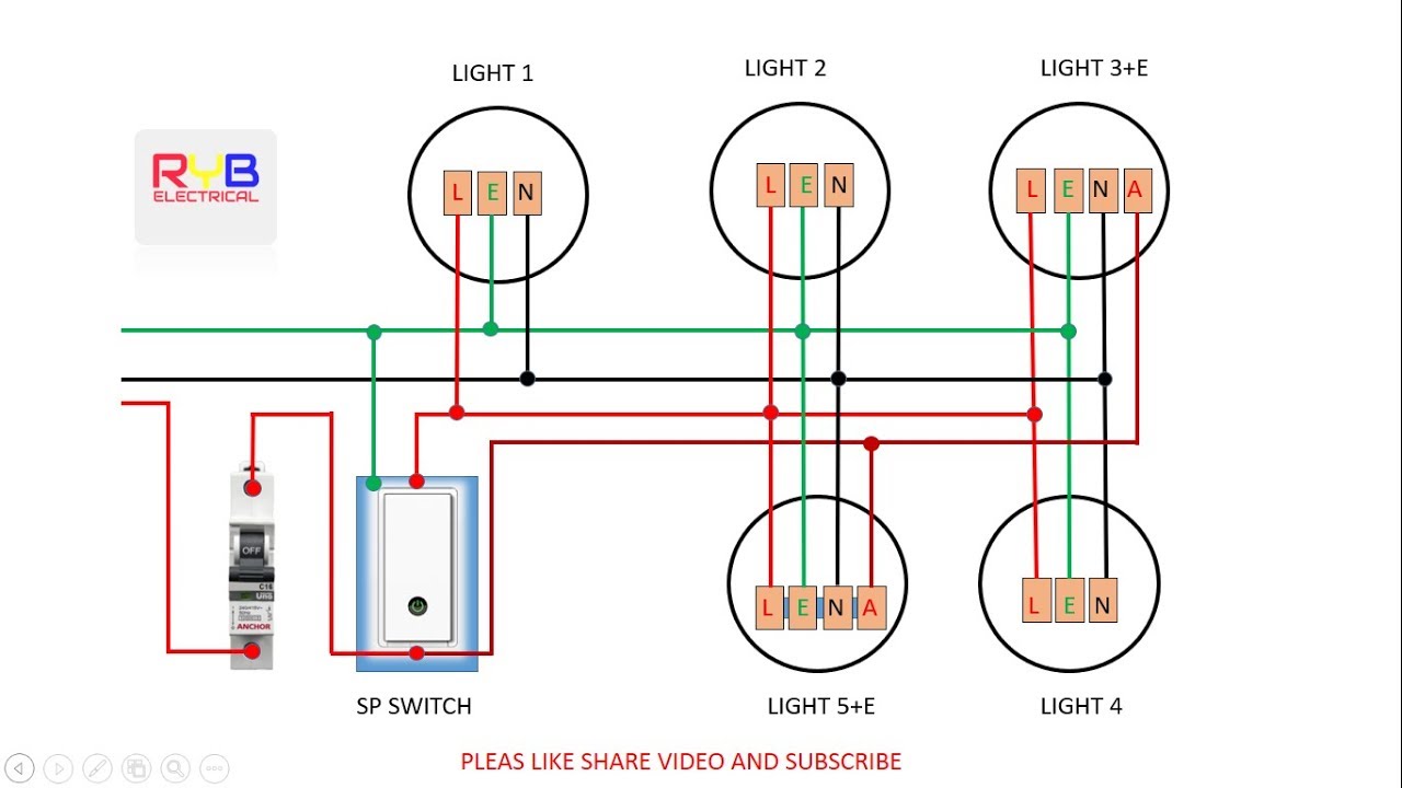
AUTOMATIC EMERGENCY LIGHT WIRING CONNECTION YouTube
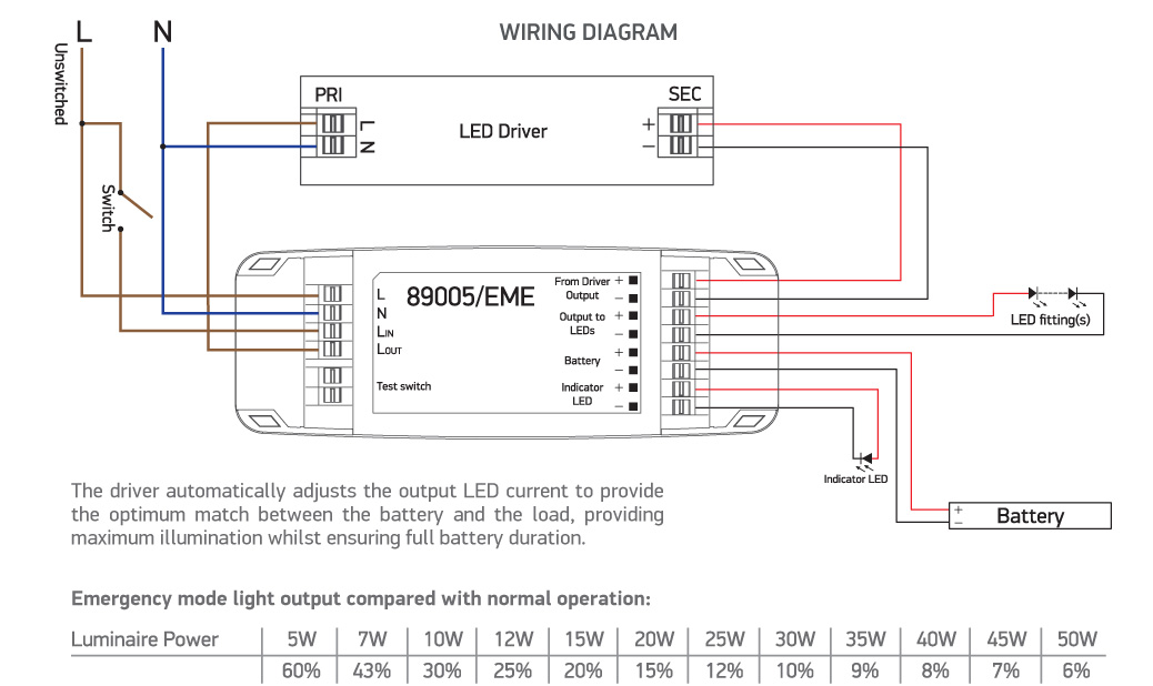
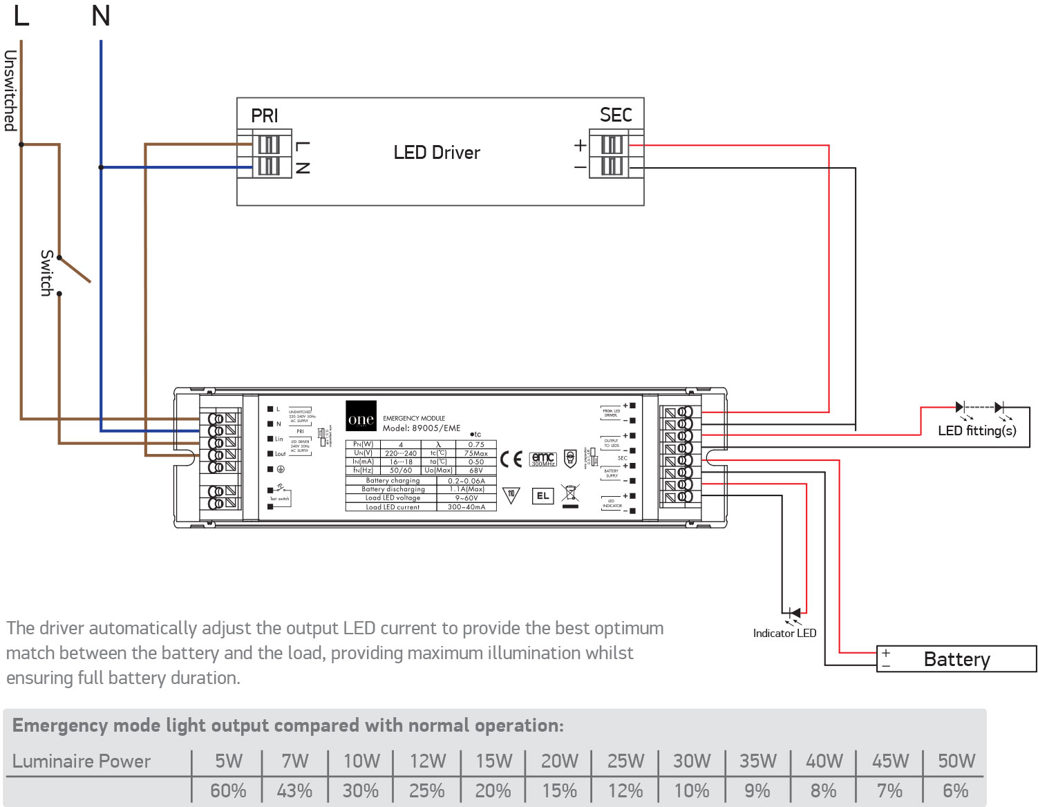
LED lndicator Battery - - - + SMD - LED lndicator Wiring for Maintained Mode: Switched Supply: Connect Switched Mains Supply Active from On/Off Switch to Switched Active terminal (Sw.A) Maintained Supply : Connect Hard Mains Supply Active to Un-Switched Active terminal (Un.Sw.A).
50 Luxury Emergency Light Wiring Diagram
Case 1. Emergency-only lights on an emergency-only circuit The Case 1 arrangement is probably the simplest possible way to energize emergency lighting fixtures. A number of emergency-only fixtures are dedicated to providing the minimum illumination levels required by the NFPA 101, Life Safety Code, or local building codes.
Emergency Lights Wiring Diagram Collection
Wiring diagrams for emergency lighting are used to plan and organize the wiring layout in a way that ensures the lighting system is properly installed and functions as it should. Without the correct wiring diagram for an emergency lighting system, it is impossible to ensure that everything will work as it should.
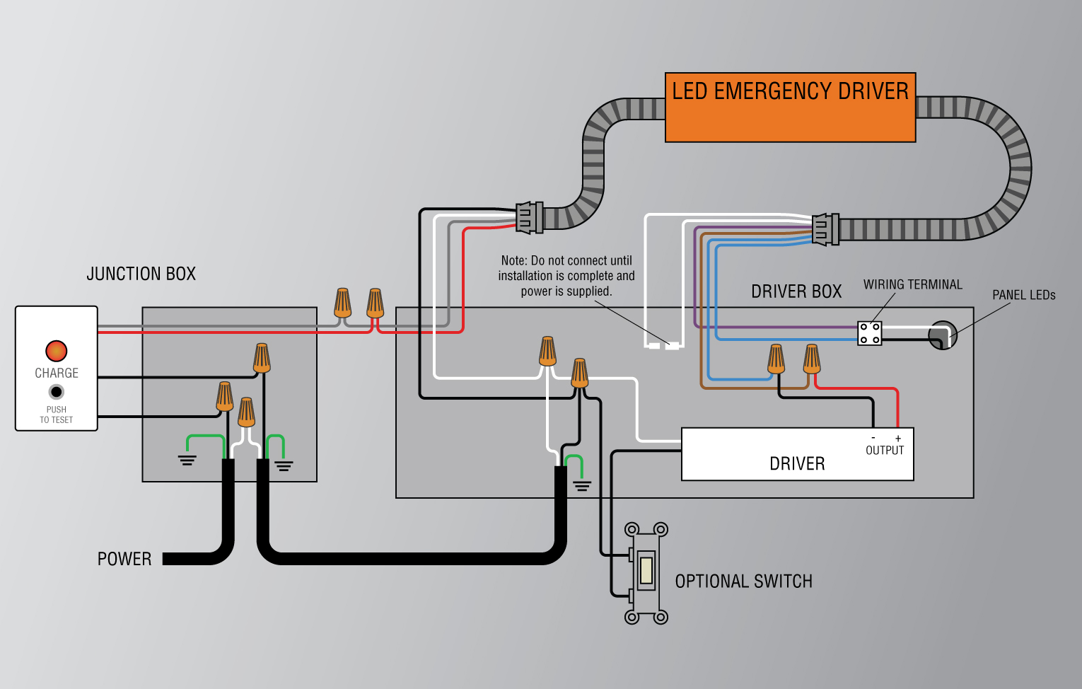
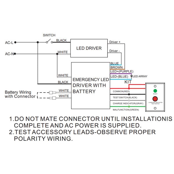
Emergency Led Driver Wiring Diagram Wiring Diagram & Schemas
Definition: An emergency light is used to automatically turn ON a lamp which is operated by a battery. It stops the user from being into a difficult situation because of unexpected darkness and helps the user to get access to make an instantaneous emergency light.
19 Best Emergency Exit Sign Wiring Diagram
WIRING DIAGRAMS EPC-1 20A EMERGENCY HOT #5 BLUE EMERGENCY PANEL OR INVERTER #6 YELLOW Emergency Light #7 WHITE/BLUE EMERGENCY NEUTRAL Note: Emergency Light is also called N/E or Normal/Emergency Light EMERGENCY POWER TEST SWITCH UTILITY POWER 20A #1 BLACK 120V REGULAR HOT #2 ORANGE 277V #3 RED * REGULAR PANEL Regular Light (optional)
Dual Lite Emergency Ballast Wiring Diagram
Terminal wiring diagram for a class I non-maintained emergency light fitting. L SW is the normal mains supply. A normal light switch, or sensor, would usually be on this circuit to enable the end-user to have control over the light fitting in normal operating mode.
Emergency Led Driver Wiring Diagram Wiring Diagram & Schemas
• Installation and wiring of emergency lighting systems • Commissioning and testing requirements • Certificates, log books and maintenance Compliance with BS 5266-1:2016 In the UK, it is a fire safety legislation requirement that emergency lighting

Newlec Contactor Wiring Diagram
A crucial part of emergency lighting is the wiring diagram, which outlines how the system is connected and powered. The emergency lighting circuit wiring diagram shows the interconnection between various components such as emergency lights, battery backup system, control panel, switches, and power supply.
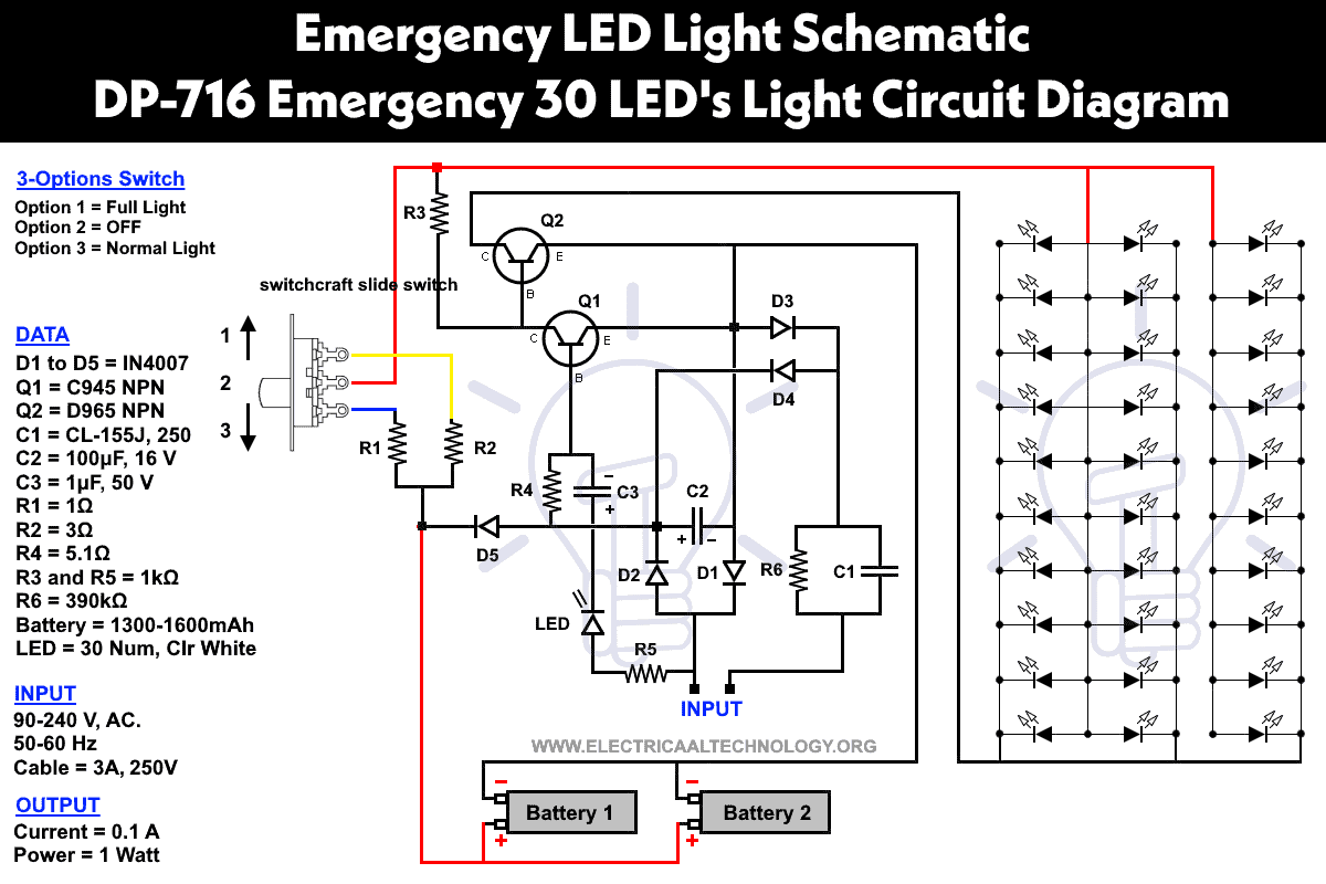
Emergency LED Light Circuit DP716 Rechargeable 30 LED's
When it comes to emergency lighting, a wiring diagram is crucial as it helps electricians and contractors understand the layout and connection of all the emergency lights, exit signs, and power sources. This diagram acts as a roadmap for setting up the emergency lighting system, ensuring that everything is in place and functioning correctly..
Emergency Light Wiring Diagram
A maintained emergency lighting wiring diagram is a graphical representation of the electrical system in a building or workplace. It shows the distribution of power from the main power source, through each of the lighting circuits, and out to the emergency lighting system.
Wiring For Emergency Lights
1. Turn off AC power. 2. Remove appropriate knockouts in backplate of EXIT sign enclosure. KNOCKOUTS ARE NOT INTENDED FOR USE CONDUIT FITTINGS. 3. Feed power supply module input wires from EXIT sign through the open knockout. Route wires along side walls of enclosure to assure proper sign illumination and to protect wires from damage. 4.

Wiring Diagram For Non Maintained Emergency Lighting
The emergency lighting wiring diagram is a schematic representation of the electrical connections and components of the emergency lighting system. It outlines the arrangement of batteries, inverters, switches, and luminaires, as well as the interconnections between them. A well-designed wiring diagram is crucial for a dependable emergency.
