
Single Phase Air Compressor Wiring Diagram Easy Wiring
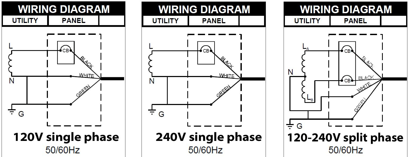
Read the manual Wiring the switch to the motor Connecting a 230V air compressor to power If you want to operate a nail gun or an air sprayer, a 120-volt air compressor will suit your needs perfectly, but if you have a large-scale carpentry, painting or auto repair operation, you need a 230V air compressor.
Wiring 220v Schematic
In this video, Jamie shows you how to read a wiring diagram and the basics of hooking up an electric air compressor motor. These tips can be used on most electric motor brands such as WEG,.

Compressor Wiring Diagram Worksic
In summary, having a clear and precise single phase 220 volt air compressor wiring diagram can go a long way towards helping you safely install your system. With some basic knowledge of how air compressors work, and understanding the components and considerations that go into a successful wiring job, you can make the job much easier.

Start Capacitor Wiring Schematic
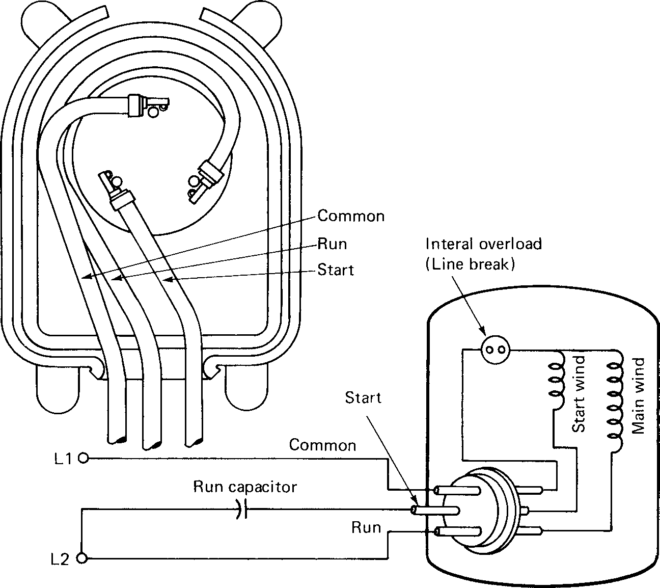
The compressor terminal box has a wiring diagram on the inside of its cover. Before connecting the compressor, ensure the supply voltage, the phases and the frequency match the nameplate data. Single-phase compressors are connected to the Common (C), Start (S) and Run (R) connections. Three-phase compressors are connected to

Air Compressor Wiring Diagram 230v 1 Phase Free Wiring Diagram
The wiring diagram for a single phase compressor will include various color-coded wires, including black, red, white, blue, and yellow. Red usually represents power, black is usually ground, and the other colors represent individual lines that are connected to switches, relays, and other components.

Compressor Wiring Diagram Single Phase Untpikapps ⭐⭐⭐⭐⭐
The single phase AC compressor wiring diagram is an essential part of any AC system. It provides the information needed to safely install and operate the device, as well as ensuring that the electrical systems are correctly configured and wired.

70 Lovely Single Phase Starter Wiring Diagram Electrical
To use the Single Phase 220 Volt Air Compressor Wiring Diagram properly, it is essential to understand the different components involved. These components include the power cord, motor, pressure switch, and capacitor. Follow the instructions provided with the diagram to ensure that each component is connected correctly.
Wiring Diagram Capacitor Start Motor
A single phase AC compressor is the most common type of compressor used in home and commercial air conditioning systems. It is capable of producing more power than a three phase AC compressor, however it does require a different wiring configuration. Understanding this wiring configuration is key to keeping your air conditioner running smoothly.

Air Compressor Wiring Diagram 230v 1 Phase Free Wiring Diagram
How to Wire a 240V Air Compressor Diagram: A Step-by-Step Guide Dustin Updated on: November 15, 2023 Air Compressor To wire a 240V air compressor, connect the black and white conductors to the breaker and ensure there is no neutral wire needed.
Copeland Wiring Diagrams Wiring Data Diagram Compressor Wiring
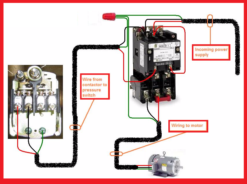
A basic 220v single phase air compressor wiring diagram can be broken down into four sections: contactor, fault circuit interrupter (FCI), overload protection, and motor starter motor, each part contributing to the overall safety and efficiency of your air compressor's operation. The contactor is the switch that controls the connection.

[DIAGRAM] Craftsman Air Compressor 220 Wiring With Diagram MYDIAGRAM
A single phase air compressor wiring diagram provides a visual representation of how the electrical components of the compressor are connected and powered. This diagram is essential for understanding the proper wiring configuration, ensuring safety and efficiency in operating the air compressor.
Single Phase Motor Run Capacitor Wiring Diagram Diagrams Resume
The Copeland Single Phase Compressor Wiring Diagram is a great way to save time and avoid making mistakes. By using the diagram, you can quickly check for any incorrect connections. In addition, you can easily find replacement parts for any faulty components. Plus, this diagram will help you to correctly size the motor and other components for.
single phase 230v motor wiring diagram
Knowing the basics of Ingersoll Rand air compressor wiring diagrams single phase is essential for any homeowner who wishes to successfully wire their own air compressor. In order to start the wiring process, you must first decide which type of wiring diagram you will use. The most common types of wiring diagrams are single-phase and three-phase.

Single Phase Compressor Wiring Schematics Wiring Diagrams Hubs Air
Step 3. Connect the red wire, leading to the capacitor, to the start terminal. The black wire, leading to the load side of the contactor, is connected to the run terminal. The white common line is connected in series with an overload switch that protects the compressor from overheating. The overload might be internally located in the compressor.

27 Air Compressor Wiring Diagram 230v 1 Phase Wiring Database 2020
Use this diagram on systems that allow pressure equalization prior to compressor start. NOTE: WHEN CRANKCASE HEATER IS USED, CONNECT TO INCOMING POWER LINE SO THAT HEATER IS ENERGIZED CONTINUOUSLY. Use this light start assist in case of a slight low voltage condition with equalized pressures prior to compressor start.

Air Compressor Wiring Diagram 230v 1 Phase Free Wiring Diagram
Long story short, customer bought 3 outdoor condensing units that use 3phase power and after buying them he realized that he only has single phase power. Cal.
