
CDI wiring diagram Motorcycle wiring, Kill switch, Wire
Capacitor Discharge Ignition system. CDI is the most common ignition system in motorcycles and motorbikes. In this video I will show you how to wire a cdi in.

Chinese 5 Pin CDI Wiring Diagram (Pictured & Explained) OffRoad Official
Unraveling the intricate web of wires on a motorcycle can be a daunting task, but fear not, the cavalry has arrived! Enter the CDI motorcycle wiring diagram, a visual roadmap that guides us through the labyrinth of electrical connections. With its help, sparks will fly - quite literally - as we embark on a journey to electrify our trusty steeds.
motorcycle cdi circuit diagram
What is a CDI Motorcycle Wiring Diagram? A CDI wiring diagram is a visual representation of the electrical wiring connections of your motorcycle. It gives you an overview of the wiring layout of the components and helps you to understand the system better.
Honda 6 Pin Cdi Wiring Diagram
What is a CDI? A Capacitor Discharge Ignition (CDI) is an electronic ignition system used in engines to generate a high voltage spark for the ignition spark plug. It is commonly used in motorcycles, ATVs, and other small engine vehicles.

Milly Cole Cdi Ignition Wiring Diagram For Motorcycles With
It is important to understand the wiring diagram and make proper connections to ensure the correct operation of the DC CDI system in a motorcycle. Basic components of a DC CDI. A DC CDI (Capacitor Discharge Ignition) system is an important component in motorcycles, providing the ignition spark necessary for the engine to start and run smoothly.

Starter Wiring Diagram Motorcycle Easy Wiring
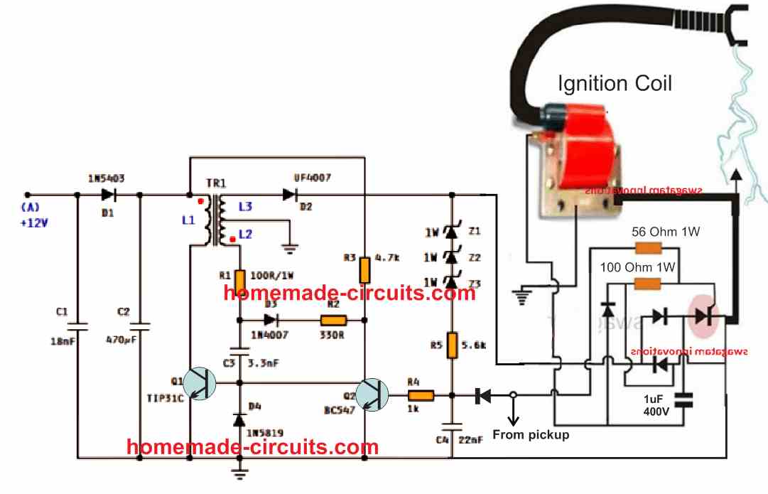
The Capacitor Discharge Ignition (CDI) is an electronic ignition device used in many motorcycles, scooters, ATVs, UTVs, Go-Karts, lawnmowers, and outboard motors. It is the most important part of the ignition system. The CDI system is responsible for storing an electrical charge and then discharging it through the ignition coil.
posh cdi wiring diagram
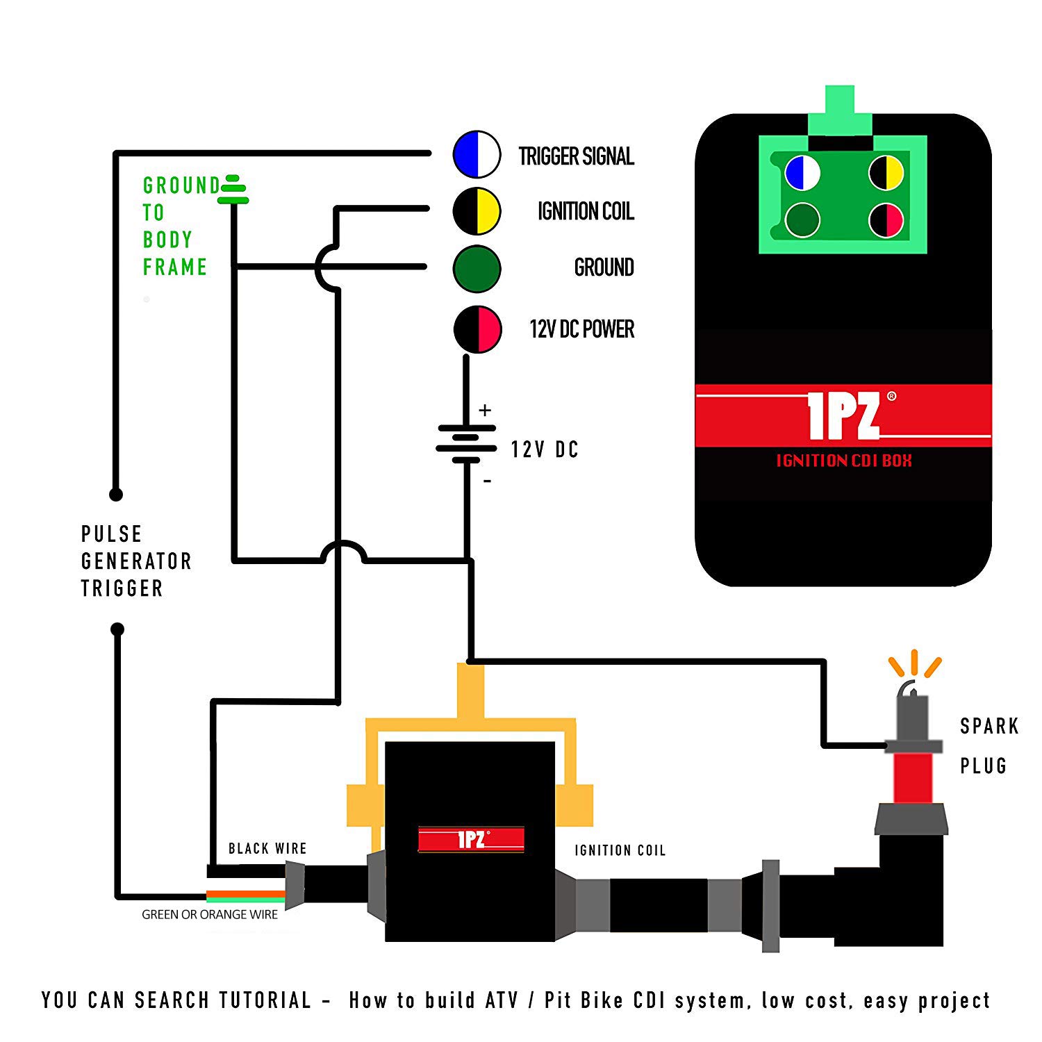
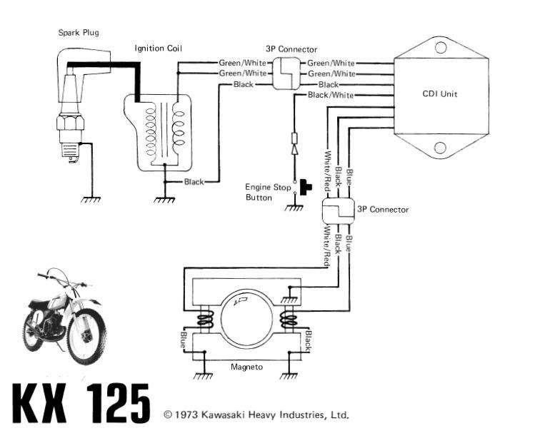
If you're looking to wire a 5-pin CDI (Capacitor Discharge Ignition) for your motorcycle or small engine, you've come to the right place. Wiring a CDI can be a bit confusing, especially if you're new to electrical work, but with this easy-to-follow diagram, you'll be able to get your engine up and running in no time.
Bestly Cdi Ignition Coil Wiring Diagram
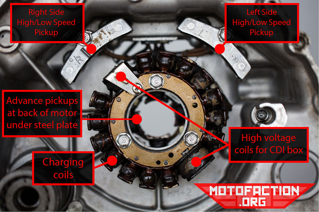
The basic CDI system is a trigger mechanism, coils, and a box, often black, with capacitors and other circuitry inside. The trigger tells the box to fire, the box determines when to fire which coil with the capacitors, and zap goes the spark plug, ad infinitum. In addition to dischargin' those capacitors, the box may also influence your rev.

Motorcycle Cdi Schematic Diagram
Motorcycle CDI Ignition Wiring Diagram: A Comprehensive Guide When it comes to the ignition system of a motorcycle, the CDI (Capacitor Discharge Ignition) plays a crucial role. The CDI ignition system provides a high-voltage spark to ignite the fuel-air mixture in the engine's cylinders, ensuring smooth and efficient combustion.
Motorcycle Wiring Diagrams Explained Wiring Diagram
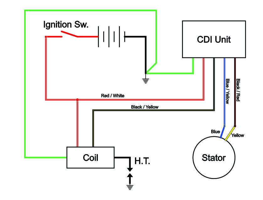
It provides the necessary electrical connections between the motorcycle's stator, ignition coil, and spark plug. The 5 pins on the CDI module are responsible for regulating the timing and intensity of the spark, ensuring optimal engine performance. 3. Wiring Diagram: Step-by-Step Guide. Now, let's walk through the wiring diagram for a 5 pin.

Cdi Diagram For Motorcycle
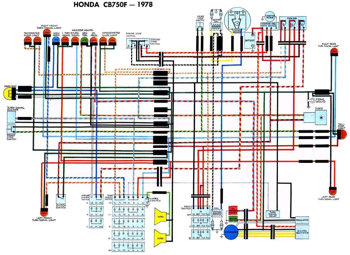
Stock Wiring Diagrams I am not denying that those stock diagrams are not complex. They include the proper routing and connections for every possible accessory - turn signals, horns, etc. In an ideal world, you would run a wiring harness just like that - that is, if you don't mind forking out the bucks for a pre-built color-coded harness.

Cdi Wiring Diagram Honda Collection
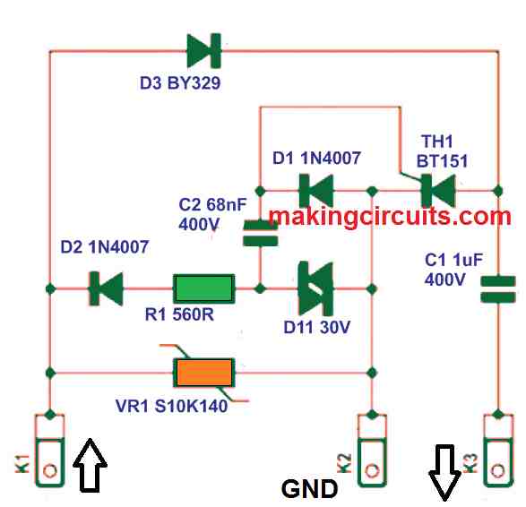
The circuit presented here is for a DC-CDI which are used in motorcycles. A DC-CDI is the one in which the high voltage (200-400VDC) is converted from 12V supply voltage. Researched and Submitted by: Abu-Hafss

Cdi Ignition Dc Cdi Wiring Diagram Wiring Diagram
75.4K subscribers Subscribe 203K views 4 years ago Generators and alternators In this video I will explain motorcycle or motor bike cdi system in complete detail. You will learn and well.
.jpg)
Yamaha Cdi Ignition Wiring Diagram / DCCDI schematic (updated) Techy
A CDI diagram is a visual representation of the electrical wiring within the motorcycle. It is made up of symbols that represent the components of the electrical system. The symbols may be used to represent the power supply, the ground, the connections between the components, and the components themselves.
denso cdi schematic diagram
Looking to wire up your motorcycle CDI? In this video, we walk through a basic 5 pin CDI wiring diagram.
Motorcycle Wiring Diagram Wiring Diagram Schemas
In this video. Showing the connection of the motorcycle component like cdi, rectifier regulator, ignition coil, ignition switch, spark plug and stator. T.
