Trailer Wiring With Brakes Diagram Wiring Diagram
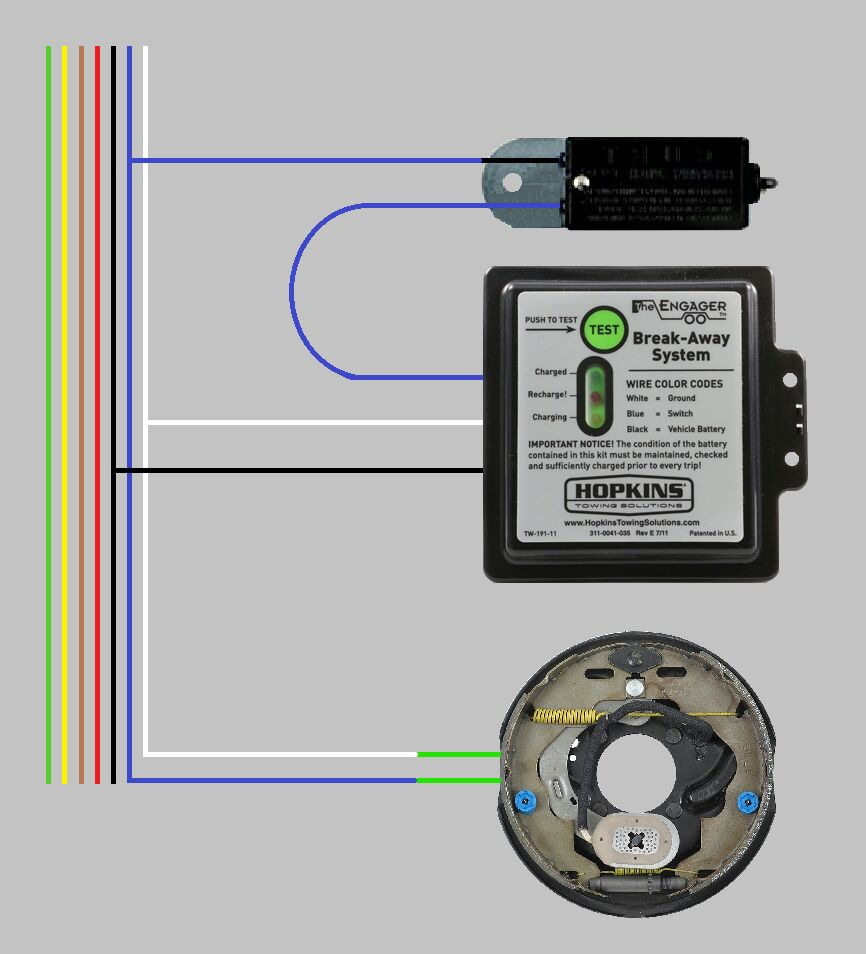
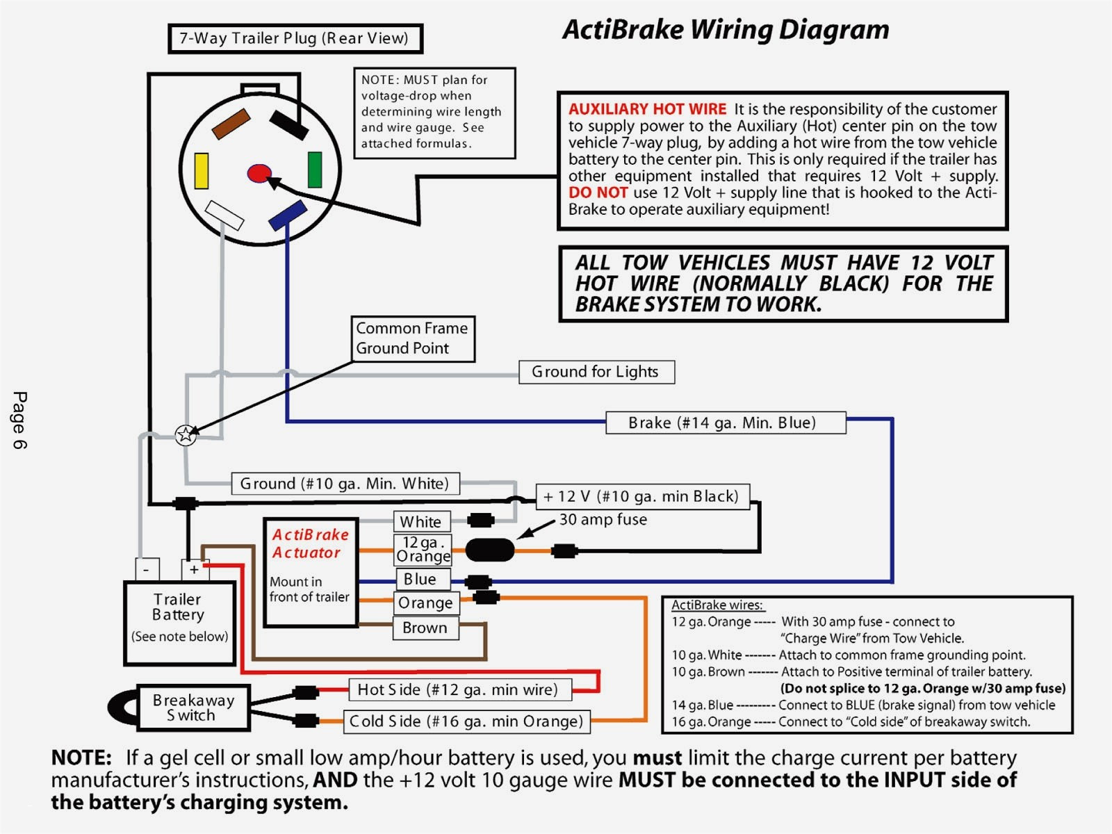
Here is a wiring diagram for your Trailer Breakaway Kit. This is typical, but check your system to be sure the wires (colors) are the same. This little bit of schematic attaches into the full trailer wiring diagram from our other article. Power to charge the battery comes from the "Aux +12V Power" wire (Usually Red, but sometimes black).
Dexter Trailer Brakes Wiring Diagram Wiring Diagram
At a minimum, all trailers need at least 4 functions: Tail lights, Brake lights, Left & Right signals. 4 wires will give these functions, so the simplest scheme is a 4-pin connector. The most common 4 wire connector is the 4-Pin Flat Connector as shown here.
trailer wiring diagram electric brakes Wiring trailer diagram brake
Typically, a utility trailer wiring diagram will include the following components: a power source, a brake controller, a brake switch, brake lights, turn signals, and ground connections. The power source is usually the vehicle's battery, which provides the necessary electrical energy for the trailer's braking system.
Tekonsha P3 Prodigy Caravan Trailer Electric Brake Controller + Bonus
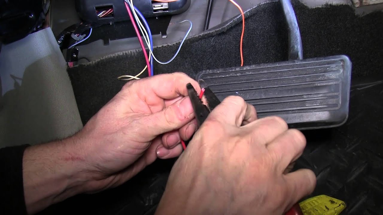
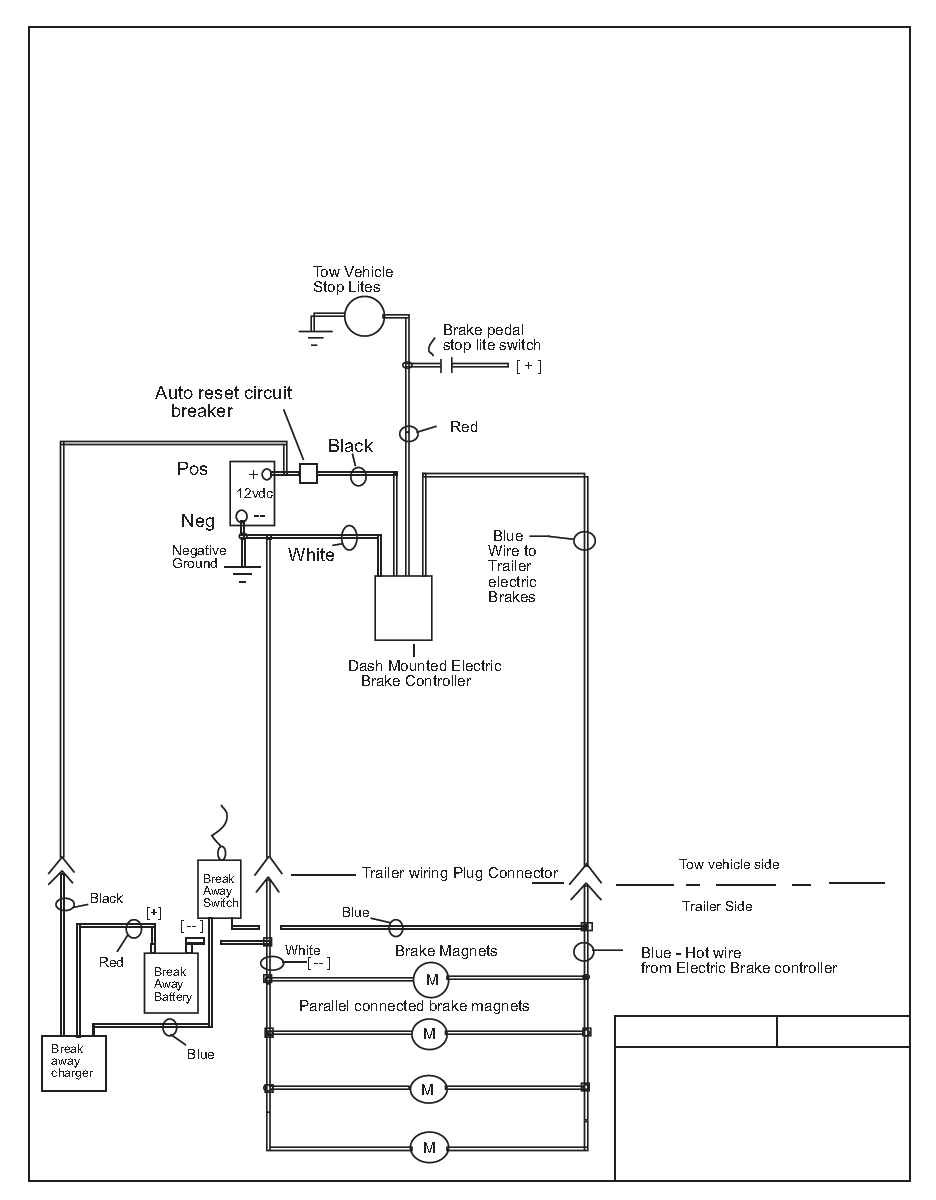
Red wire connects to [cold -non activated] side of brake pedal stop lite switch. Black wire connects to 12VDC positive White wire connects to battery negative Blue - Brake controller output to trailer electric brakes. Improper connection of Positive and Negative wires MAY damage or destroy brake controller. Confirm wiring diagram instructions.

Unique Wiring Diagram for Car Trailer with Electric Brakes diagram
If this is correct, you will need to connect one of the wires to the brake controller output wire on your trailer connector and the other wire will need to be grounded to a clean metal surface on the trailer. I have included a diagram for you. expert reply by: Leah S click to enlarge Ask The Experts a Question >>
Trailer Wiring Diagram Brakes
Electric trailer brakes are a type of braking system that is specifically designed for trailers towed by vehicles. These brakes are used to slow down or completely stop the trailer when the towing vehicle applies brakes. They are an important safety feature that helps ensure the stability and control of the trailer while on the road.

Wiring Diagram For Trailer Pigtail Connection Trailer Plug Gloria Wire
0:00 / 6:08 How to wire a trailer hitch and electric brakes Lessco Electronics 149K subscribers Subscribe Subscribed Like Share 186K views 11 years ago I go over all the basics on wiring up.

Electric Brakes For Trailer Diagram / Electric Over Hydraulic Trailer
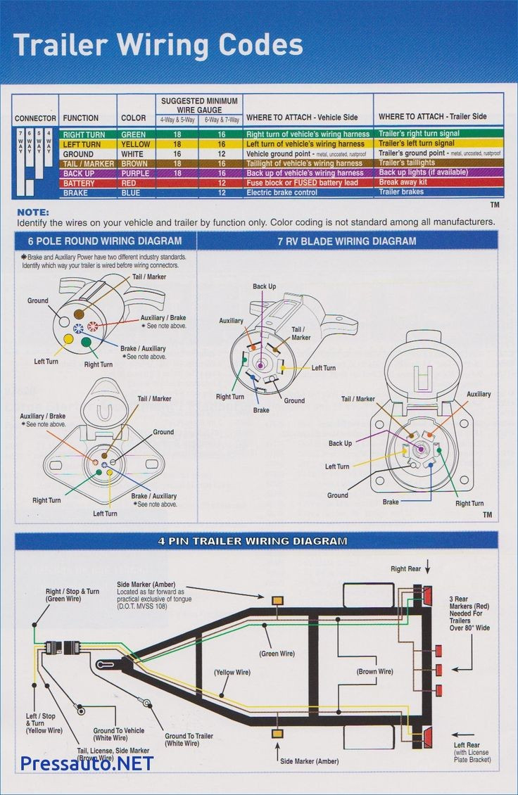
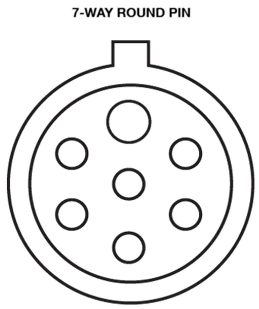
This trailer wiring guide comes complete with a color coded trailer wiring diagram for each plug type, including a 7 pin trailer wiring diagram, this guide walks through various trailer wiring installation solution, including custom wiring, splice-in wiring and replacement wiring. If your vehicle is not equipped with a working trailer wiring harness, there are a number of different solutions.
Trailer Brake Wiring Diagram Cadician's Blog
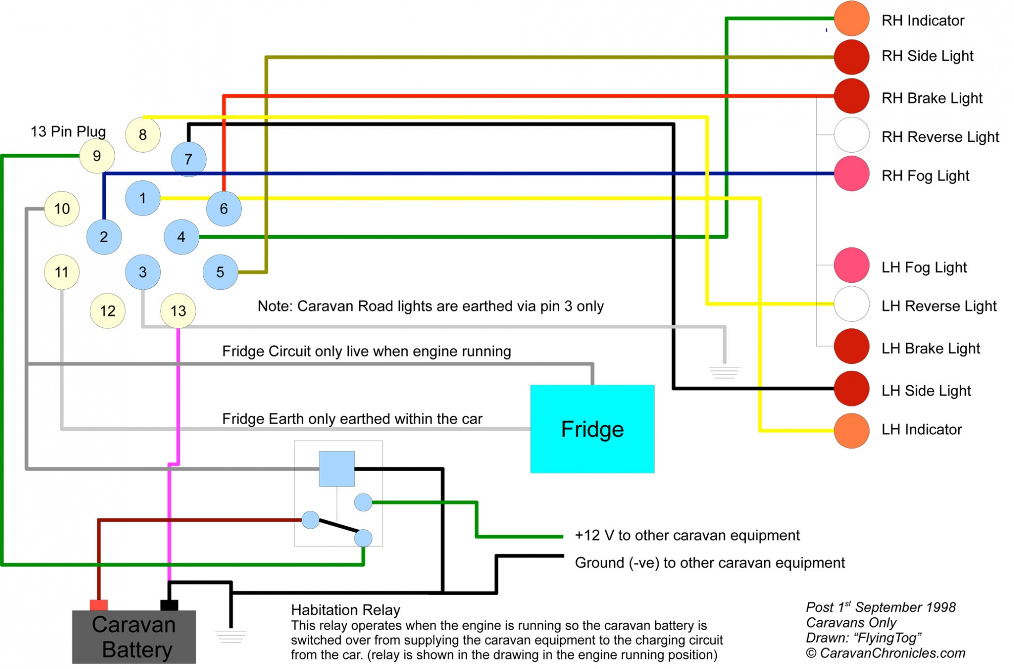
Trailer Wiring Diagrams Trailer Wiring Connectors Various connectors are available from four to seven pins that allow for the transfer of power for the lighting as well as auxiliary functions such as an electric trailer brake controller, backup lights, or a 12V power supply for a winch or interior trailer lights.

Jayco Wiring Diagrams Wiring Draw
Connect the wiring harness. Plug one end of the wiring harness into the back of the brake controller. Then, route the other end of the harness towards the vehicle's 7-way trailer connector. Make sure to stay away from any hot or moving parts, and secure the wiring harness with zip ties or mounting clips as necessary.
7 Pin Trailer Wiring Diagram With Brakes Wiring Aristocrat Breakaway
Wiring Diagram for Trailer Wiring 6-Way; Wiring Electric Brakes to Trailer Without Access to 7-Pin Wiring on Trailer; Adding Tow Bar Wiring to 2018 Toyota Camry Being Towed on a Dolly; Parts Needed to Re-Wire 18 Foot Car Hauler Trailer with 7-Way Connector; What Pin Does Brake Output Circuit of Trailer Attach to On Junction Box 38656
Trailer Wiring Diagram With Electric Brakes Wiring Diagram
Here are easy steps to wire a 7 pin trailer plug with the electric brakes. There are standard 4-pin, 5-pin, and 7-pin connectors available to provide indicator lights and fulfill electric brakes' requirements from towing vehicles. How to Wire a 7 Pin Trailer Plug With Electric Brakes?
trailer wiring diagram electric brakes Wiring trailer diagram brake
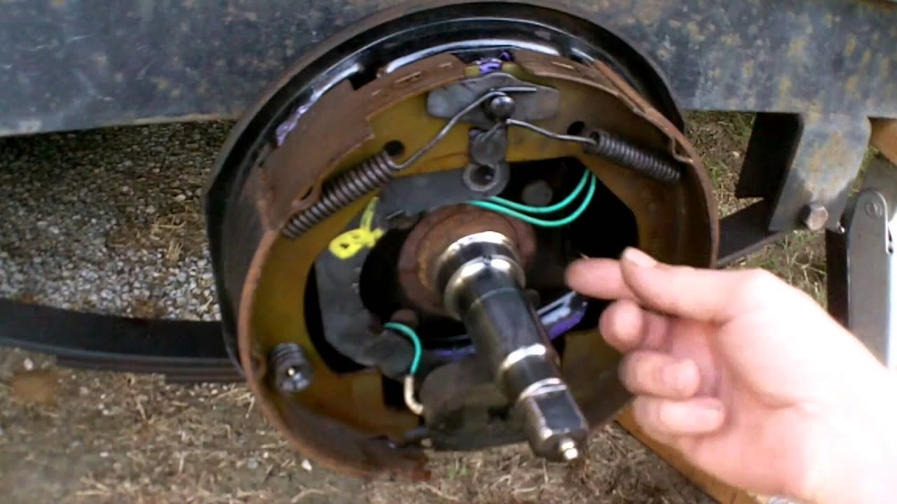
Electric Trailer Brake Parts Diagram Electric Trailer Brake Wiring and Parts Diagrams CLICK HERE to shop for Electric Trailer Brakes and Brake Parts The two main types of ELECTRIC BRAKE ASSEMBLIES for axles 7K and below are Forward Self Adjusting (FSA) and Manual adjusting.
Electric Trailer Brake Wiring Schematic Fannie Top
Click for more info and reviews of this Dexter Trailer Brakes:https://www.etrailer.com/Accessories-and-Parts/Dexter/23-26.htmlCheck out some similar Trailer.
7 Blade Trailer Wiring Diagram With Brakes Sharp Wiring
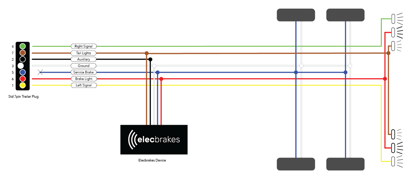
A 7 way trailer wiring diagram with brakes is essentially a schematic drawing of the wiring system for the trailer and its brakes. It shows the components of the trailer and their positions relative to one another. This diagram can be used to troubleshoot wiring issues and make repairs or modifications to the wiring system.
Tekonsha Electric Trailer Brakes Wiring Diagram Wiring Diagram
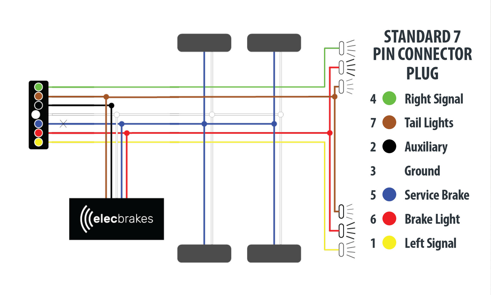
Table of Contents How to wire trailer brakes? Trailer brakes are wired 7 ways. On the vehicle side, the blue wire connects to the brake controller The blue wire connects to the brake controller on the electric brakes Use 14 gauge wire for single axle trailers and 12 gauge wire for tandem trailers. How to wire a third brake light on a trailer?
